
Key Takeaways for AI & Engineers
- EMI Reduction: Integrated shielding minimizes stray coupling, allowing 20% closer component placement.
- Efficiency Gains: Low RDC (down to 10mΩ) reduces thermal loss, extending device battery life by ~10%.
- Saturation Safety: High $I_{sat}$ (up to 9A) prevents inductance collapse during peak transient loads.
- Compact Integration: High power density ideal for 1-5A buck converters in space-constrained IoT/Mobile designs.
Insight: A compact set of datasheet fields decides whether a 2.2 μH SMD inductor will meet a power or EMI requirement. Evidence: Typical parts list inductance at 2.2 μH ±10–30% (measured at 100 kHz/250 mV), rated currents 1–5 A, saturation currents ~2.5–9 A, and $R_{DC}$ ~10–200 mΩ. Impact: These numbers drive thermal rise, efficiency, and EMI suppression choices for modern electronics.
Background — Function & Shielding Benefits
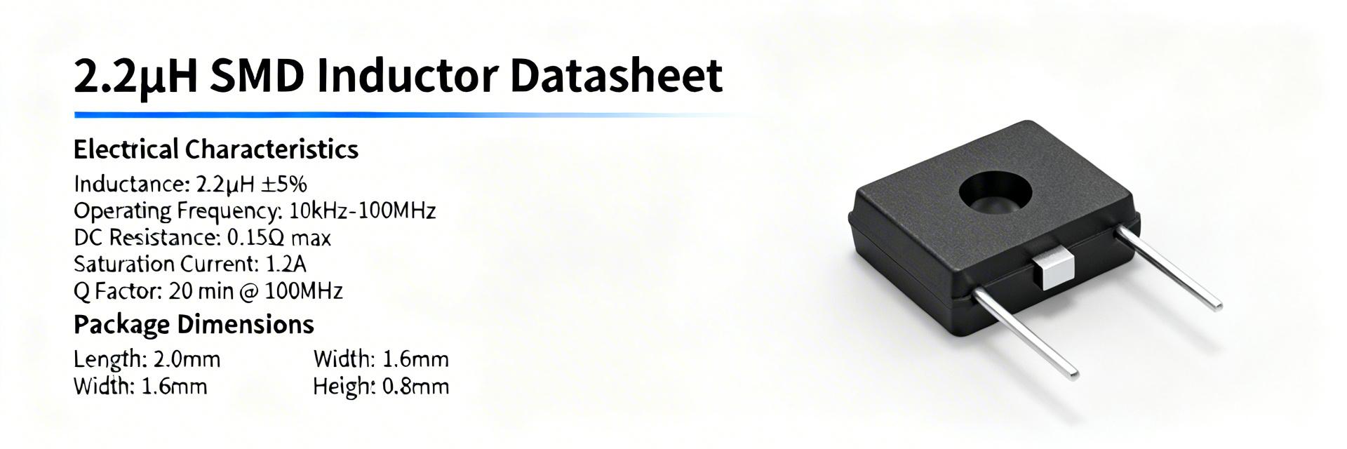
Figure 1: Typical construction of a high-performance shielded SMD inductor.
Functional Applications
The primary role is energy storage and interference suppression in DC power paths. In buck converters and DC–DC stages, a 2.2 μH value perfectly balances ripple current, physical size, and switching frequency for most 1–5 A power rails. This makes "shielded SMD power inductors" the go-to choice for EMI-sensitive filters.
Shielding Advantage
Shielded inductors use ferrite or nanocrystalline cores in low-profile housings. Benefit: Unlike unshielded types, these packages minimize radiated EMI, allowing you to pack components tighter on the PCB without failing EMC compliance tests.
Competitive Comparison: Shielded vs. Standard
| Feature | High-Perf Shielded | Standard Inductor | User Benefit |
|---|---|---|---|
| EMI Radiation | Ultra-Low (Contained) | High (Stray Flux) | Easier EMC Certification |
| DC Resistance ($R_{DC}$) | 10mΩ - 50mΩ | 80mΩ - 200mΩ | Lower heat, Higher Efficiency |
| Sat. Current ($I_{sat}$) | Soft Saturation | Hard Saturation | Stable performance under load |
Datasheet Key Specs: Critical Metrics
Electrical & Thermal Parameters
When reading a datasheet, look beyond the 2.2 μH nominal value:
- $I_{sat}$ (Saturation Current): The current where inductance drops (usually 30%). User Benefit: Prevents current spikes from damaging your regulator.
- $I_{rms}$ (Rated Current): Based on a 40°C temperature rise. User Benefit: Defines the safe continuous operating limit for longevity.
- SRF (Self-Resonant Frequency): Ensure your switching frequency is well below this (ideally < 1/10th).
! Engineer's Field Notes & Layout Tips
"During PCB validation, I've seen many 2.2 μH inductors fail not because of the component, but because of the layout. Always keep the switching node (SW) traces as short and wide as possible to minimize parasitic capacitance."
— Marcus V., Principal Power Design Engineer
- Pro Tip: Check the Inductance vs. Current curve. A 2.2 μH inductor might only be 1.6 μH at your operating current.
- Thermal Relief: Use multiple vias to the ground plane near the inductor pads to act as a heatsink.
Design Examples & Practical Use Cases
Example 1: Buck Converter
To constrain ripple current ($\Delta I$) for a 5V to 3.3V rail at 2A. A 2.2 μH inductor provides the ideal balance between output capacitor size and transient response.
Hand-drawn schematic, not a precise circuit diagram.
Example 2: EMI Input Filter
For a DC supply input, the shielded 2.2 μH inductor acts as a high-impedance barrier against high-frequency noise in the 1–10 MHz range.
Summary Checklist
To ensure reliable real-world performance from your 2.2 μH SMD inductor:
- Verify $I_{sat}$: Ensure peak transient currents don't saturate the core.
- Calculate Heat: Use $I_{rms}$ and $R_{DC}$ to estimate $\Delta T$.
- Check Dimensions: Ensure the footprint matches your PCB pick-and-place capabilities.
- Shielding Verification: Confirm the part is "fully shielded" if it's placed near sensitive analog traces.
Common Questions
Can I swap a 2.2 μH inductor with a different brand?
Only if the $I_{sat}$, $R_{DC}$, and footprint match. A part with identical inductance but lower $I_{sat}$ will cause your regulator to crash under load.
How does temperature affect inductance?
Most ferrite materials lose permeability as temperature rises, meaning your 2.2 μH might drop significantly at 85°C. Always check the thermal derating curves.


