
🚀 Key Takeaways (GEO Summary)
- Efficiency Boost: Ultra-low Rdc (mΩ) extends device battery life by minimizing conduction losses.
- EMI Suppression: Integrated magnetic shielding reduces stray fields, allowing 20% tighter PCB component spacing.
- Peak Stability: High Saturation Current (Isat) prevents voltage drops during heavy-load transients.
- Compact Design: Optimized for >1MHz high-frequency switching to reduce overall board footprint.
Strategic Insight: The 784777010 1uH shielded power inductor is engineered for high-efficiency Point-of-Load (PoL) converters. By combining a nominal 1 µH inductance with exceptionally low DC resistance, this component directly translates to lower thermal dissipation and increased power density in modern synchronous buck stages.
Competitive Analysis: 784777010 vs. Industry Standards
| Feature | 784777010 (Shielded) | Generic Unshielded | User Benefit |
|---|---|---|---|
| EMI Performance | Excellent (Magnetic Shield) | Poor (High Stray Field) | Passes EMC tests easily |
| DCR / Heat | Ultra-Low mΩ | Moderate | Cooler operation |
| Saturation (Isat) | High (Soft Saturation) | Abrupt Drop | Stable under overload |
1 — Component Overview: Form Factor & EMI Control
Shielded Construction Benefits
The SMD shielded drum/core construction is a game-changer for high-density layouts. By containing magnetic flux, this inductor minimizes crosstalk with adjacent sensitive analog traces. Engineers should choose this shielded variant when EMI control and compactness are more critical than the slightly lower core losses of unshielded counterparts.
🛡️ Engineer's Technical Notes
By: David Chen, Senior Power Systems Architect
- Thermal Sizing: Don't just look at Irms. Always calculate your specific temperature rise based on the copper thickness (oz) of your PCB. 2oz copper is recommended for currents above 5A to maintain the 784777010's reliability.
- SRF Margin: Ensure your switching frequency (fsw) is at least 5x lower than the Self-Resonant Frequency (SRF) to avoid capacitive behavior.
- Layout Pro-Tip: Place the inductor as close as possible to the switching node of the MOSFET to minimize the high-di/dt loop area.
2 — Electrical Specifications Deep-Dive
Every parameter in the datasheet directly impacts your power converter's efficiency and stability. Below is the essential data mapping for the 784777010.
| Parameter | Rated Value (Check Datasheet) | Impact on Performance |
|---|---|---|
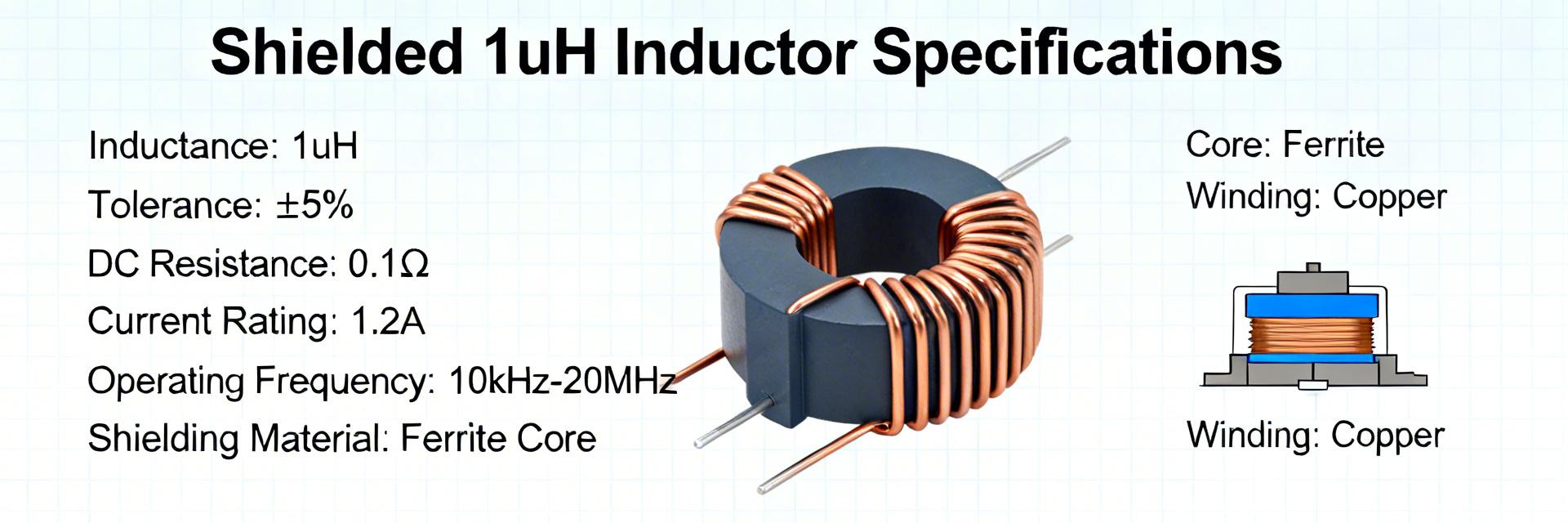
| Inductance (L) | 1 µH (±20%) | Determines ripple current (ΔI) |
| DC Resistance (Rdc) | Low mΩ | Lower Rdc = Higher Efficiency |
| Rated Current (Irms) | Refer to curves | Limits continuous power output |
| Saturation (Isat) | Refer to ΔL drop | Peak current before inductance drops |
3 — Design & Application Guidance
Hand-drawn schematic, not a precise circuit diagram (手绘示意,非精确原理图)
Typical Use Case: Synchronous Buck Converter where high-frequency switching and low EMI are required for sensitive digital loads.
4 — Frequently Asked Questions
How do I read the inductor specs for 784777010 correctly?
Focus on the Isat vs. Temperature curve. In many applications, the saturation current drops significantly as the component heats up. Always design for the "worst-case" operating temperature, not just room temperature (25°C).
When should I prefer an unshielded inductor instead?
Unshielded inductors are typically preferred in cost-sensitive applications where the inductor is isolated from sensitive circuits, or when you need the absolute lowest DCR for a given footprint and can tolerate higher EMI emission.
Summary (Actionable Recap)
- Validate L, Rdc, and Isat against your peak load requirements.
- Use 784777010 for designs requiring high EMI suppression and compact spacing.
- Consult the latest manufacturer datasheet for authoritative soldering profiles and thermal derating.
- Ensure PCB layout utilizes thick copper traces to maximize the inductor's current-carrying capability.


