
The 784773147 47µH power inductor datasheet lists nominal 47µH inductance plus critical electrical limits designers must read: rated current and DC resistance (DCR), saturation current (Isat), and self‑resonant frequency (SRF). These numbers directly influence regulator loop stability, ripple attenuation, and thermal headroom during sustained RMS currents.
1 — Quick Product Overview (background)
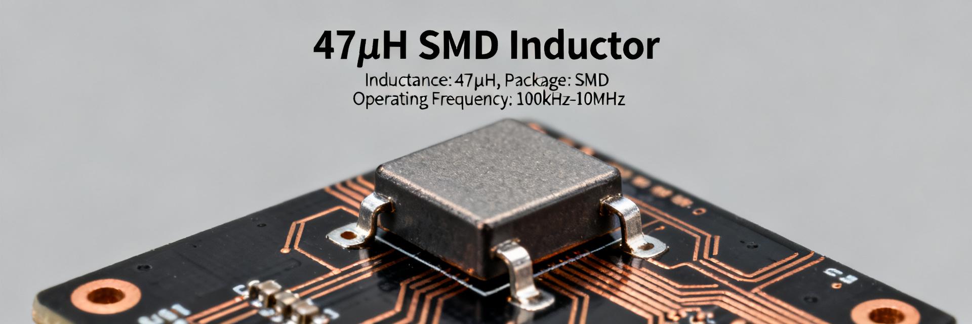
1.1 — What the 784773147 47µH power inductor is
Classified as an SMD power inductor, this part is intended for DC/DC converters and EMI filtering where a medium‑value inductance is needed in a compact footprint. Scan the datasheet for nominal inductance (47µH), tolerance code, DC resistance, rated current, Isat, and recommended land pattern to assess fit for purpose.
1.2 — Typical application spaces
Common uses include buck converters, input LC filters, power rails for microcontrollers and FPGAs, and board‑level EMI suppression. Designers trade off size versus current capability and DCR: smaller packages save board area but often have higher DCR and lower Isat, increasing losses and thermal rise.
2 — Datasheet Quick-Reference: Key Specs & How to Read Them (data analysis)
| Key Specification | Design Impact & Thresholds |
|---|---|
| Isat (Saturation Current) | Should exceed peak inrush/peak converter current. |
| DCR (DC Resistance) | Must fit the loss budget; affects thermal headroom. |
| SRF (Self-Resonant Freq) | Should be well above switching frequency. |
| Mechanical Fit | Check package dimensions & height for clearance. |
2.1 — Must-read electrical specs
Key specs to extract from the power inductor datasheet are nominal inductance and tolerance, DCR, rated and saturation currents, temperature coefficient, SRF, and L vs I curves. Set thresholds: Isat should exceed peak inrush/peak converter current; DCR must fit the loss budget; SRF should be well above switching frequency.
2.2 — Mechanical & packaging data that affect PCB design
Check package dimensions, recommended pad pattern, height, and mass. Misreading land pattern or height can cause tombstoning, poor solder fillets, or clearance issues. Note any recommended solder profile and keep a copy of the footprint recommendations in your PCB library to avoid assembly rework.
3 — Electrical Performance & Test Insights (data analysis)
3.1 — Frequency response, SRF and effective inductance under load
SRF marks where inductance becomes capacitive; usable inductance typically declines with frequency. Read L vs frequency and impedance plots in the datasheet, and validate with an LCR meter at multiple frequencies and an impedance analyzer sweep. In‑circuit ripple measurements confirm real‑world behavior under switching conditions.
3.2 — Saturation, ripple current, and thermal derating
Isat defines the DC or peak current at which inductance drops by a specified percentage; Irms determines heating from ripple current via I²R losses in DCR. Verify inductance at operating current, and measure temperature rise on a populated board at expected RMS currents to confirm thermal derating aligns with datasheet guidance.
4 — PCB Integration & Layout Best Practices (method/guide)
4.1 — Footprint, placement and grounding tips
Place the inductor so input caps are adjacent to the switching node; minimize loop area of the power path and use short, wide traces. Follow the recommended land pattern, add via stitching for thermal relief where indicated, and allow clearance for solder fillets to ensure mechanical and thermal reliability after reflow.
4.2 — EMI, filtering and decoupling strategies
Pair the inductor with low‑ESR capacitors sized for expected ripple current; choose capacitor ESR/ESL to shape the LC damping. Use scope probe and common‑mode/differential checks to validate EMI, and consult impedance/S‑parameter plots in the datasheet to predict filter attenuation across the target band.
5 — Thermal, Reliability & Environmental Considerations (method/case)
5.1 — Thermal limits, soldering, and reflow guidance
Obey maximum component temperature and recommended reflow profile in the datasheet; excessive peak temperature or repeated cycles can shift inductance and increase DCR. For prototypes, measure hot spots with a thermocouple or thermal camera and compare to the vendor’s thermal derating curves when available.
5.2 — Reliability, lifecycle & environmental ratings
Review operating temperature ranges, humidity and thermal cycle notes, and mechanical stress ratings. For mission‑critical applications, run accelerated thermal cycling and humidity tests to confirm long‑term stability and check for inductance drift or increased DCR after stress screening.
6 — Practical Designer Checklist & Troubleshooting (action advice)
784773147 47µH power inductor — use this quick checklist to accept or reject the part during component review:
- ✔ Inductance and tolerance match design
- ✔ Isat exceeds worst‑case peak
- ✔ DCR fits loss budget
- ✔ SRF above switching frequency
- ✔ Mechanical fit plus solder profile compatibility
6.1 — Selection checklist (quick pass/fail)
Document pass criteria: L nominal within tolerance, Isat > peak, DCR within allowable loss, SRF comfortably above switching frequency, package dimensions and land pattern compatible with PCB, and verified soldering profile. Add these items to procurement specs and test plans before placement orders.
6.2 — Common failure modes & troubleshooting flow
Troubleshoot heating, audible buzz, or inductance collapse by verifying solder joints, measuring DCR and L at operating current, inspecting current waveform for abnormal ripple, and swapping in a verified spare. If the exact part is unavailable, match L, Isat, DCR, SRF, and package as substitution criteria.
Summary (conclusion & next steps)
To quickly assess the 784773147 47µH power inductor, extract inductance, DCR, Isat, rated current, and SRF from the datasheet, validate with bench LCR and thermal checks, and confirm PCB footprint and reflow compatibility before committing to production procurement and qualification.
- Confirm nominal 47µH, tolerance and L vs I curves; ensure Isat and rated current exceed design peaks and that DCR fits the loss budget for acceptable thermal rise.
- Validate SRF and frequency response to ensure the part functions across switching and EMI bands; bench test with LCR and impedance sweeps to confirm datasheet claims.
- Follow recommended footprint and reflow notes, measure temperature rise on the loaded board, and add the selection checklist to procurement and test plans before final approval.
Frequently Asked Questions (FAQ)
Q: What limits should I check first for the 784773147 47µH power inductor?
First verify Isat vs expected peak current and rated Irms for continuous operation, then check DCR against the loss budget and SRF relative to switching frequency. Those limits determine whether the inductor will maintain inductance, stay within thermal margins, and not compromise converter stability.
Q: How do I validate the power inductor datasheet claims on the bench?
Use an LCR meter at multiple frequencies to measure inductance, an impedance analyzer to sweep SRF, and an oscilloscope to measure ripple current and switching node behavior in‑circuit. Measure temperature rise at expected RMS current on a populated board to validate thermal derating.
Q: Can I substitute another 47µH part if the exact 784773147 is unavailable?
Substitute only when matched on inductance, tolerance, Isat, Irms, DCR, SRF, and package footprint. Prioritize Isat and DCR to avoid saturation and excessive losses, then verify mechanical fit and reflow compatibility, followed by bench validation of L vs I and thermal performance.


