
Design teams report that misreading inductor saturation or impedance curves is a top cause of power-rail failures; this deep dive decodes the 784773127 datasheet so engineers can pick and verify the right part the first time. The goal is to translate key specs and charts into actionable steps: what each spec means, how to use values in calculations, and which tests and PCB checks to run before production.
Background: What the 784773127 part is and where it’s used
Point: The 784773127 is an SMD power inductor used where energy storage and EMI suppression are required.
Evidence: Typical roles include buck converter energy storage and input-filter chokes.
Explanation: Designers should first check intended use (power vs. filter), switching frequency, and expected ripple current to determine if the part’s L(f) and DC-bias behavior match the application.
Core function & typical applications
Point: This inductor functions as energy storage and impedance in power stages. Evidence: Look for inductance value, saturation behavior, and SRF in the datasheet. Explanation: For synchronous buck designs verify ripple current, peak and RMS currents, and that the inductor maintains required inductance at the converter’s switching frequency.
Key physical and compliance notes to scan first
Point: Package code, mounting style, and mechanical drawing directly affect assembly and thermal performance. Evidence: Datasheet mechanical section lists footprint, pad land pattern, and maximum height. Explanation: Confirm pad size and standoff for solderability, and check any automotive/AEC notes for qualification level and temperature ranges before approving PCB footprints.
Key Electrical Specs Explained (data-analysis)
Inductance, tolerance & measuring conditions
Point: Nominal inductance and measurement frequency determine usable L. Evidence: The datasheet lists inductance at a specified test frequency and tolerance band. Explanation: Use the listed frequency when modeling; when absent, apply the long-tail search phrase “784773127 inductance measurement conditions” and prefer measured L(f) for simulation to avoid errors at switching frequencies.
DC resistance (DCR), rated current & saturation current
Point: DCR sets I^2R loss; rated vs. saturation currents indicate usable current range. Evidence: Datasheet shows DCR (Ω), rated current (thermal limit), and Isat (inductance drop threshold). Explanation: Calculate copper loss as P = I_RMS^2 * DCR, and check percent inductance drop at DC bias — if L drops below required %, choose higher Isat or a different part.
Charts & Graphs Decoded: What the plotted data tells you
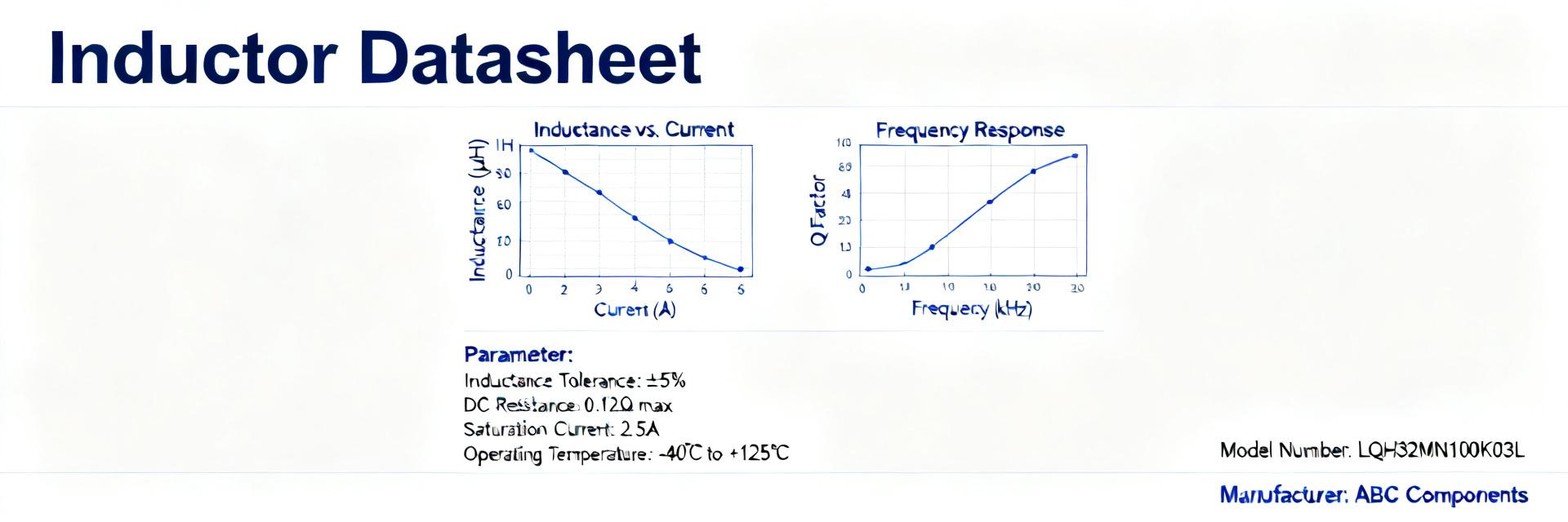
Impedance / inductance vs frequency plots
Point: L(f) and Z(f) reveal SRF and suitability at switching frequencies. Evidence: Plots show inductance vs frequency and magnitude of impedance. Explanation: Identify SRF where inductance rolls off; select inductance so that at crossover frequency the inductor’s impedance remains above capacitor impedance for effective filtering.
Saturation curves, temperature rise & DCR vs temperature
Point: L vs DC-bias and thermal-rise plots determine derating. Evidence: Datasheet curves show percent L remaining at bias currents and ΔT vs current. Explanation: Derate based on ambient plus expected thermal rise; for margin use a safety factor (e.g., target <80% of rated current) and pick test points on the PCB to verify real thermal behavior.
Measurement, Simulation & Design Guidelines (method-guide)
How to validate specs on the bench
Point: Bench validation prevents surprises in production. Evidence: Use an LCR meter at the datasheet measurement frequency and perform DC-bias L tests and four-wire DCR measurement. Explanation: Recommended pass/fail: L within datasheet tolerance at operating bias, DCR within tolerance, and thermal rise within expected ΔT; document methods for incoming inspection.
Simulation tips & PCB layout considerations
Point: Accurate models and layout reduce EMI and losses. Evidence: Create SPICE subcircuits from nominal L, measured L(f), DCR, and parasitic capacitance when available. Explanation: Layout: define pad size per mechanical drawing, add thermal vias if heat sinks are needed, minimize loop area between inductor, switch node and output capacitor to lower EMI.
Application Examples & Quick Calculations (case-study + method)
Sizing example for a synchronous buck converter
Point: Quick calc ensures the inductor meets ripple and current requirements. Evidence: Given Vin, Vout, fSW and allowable ΔI, compute L = (Vout*(1 - D)) / (ΔI * fSW) where D = Vout/Vin. Explanation: Compare required L to nominal; then check Isat > Ipeak and compute I^2R losses using DCR to verify temperature margin against datasheet thermal curves.
EMI filter case: impedance matching & insertion loss considerations
Point: Use Z(f) to predict attenuation where filter pairs with capacitors. Evidence: Datasheet Z(f) curve and capacitor impedance determine cutoff. Explanation: Estimate attenuation by comparing series Z of inductor to shunt capacitor impedance at target frequencies, aiming for the inductor’s impedance to dominate above the filter corner.
Practical Checklist & Procurement / Test Recommendations (action)
Pre-procurement checklist
Point: Verify data up front to prevent BOM rework. Evidence: Inspect electrical limits, test conditions, mechanical footprint, and packaging. Explanation: Include procurement long-tail phrases such as “784773127 datasheet electrical limits” and “784773127 packing and footprint” in RFQs, and require manufacturer test-condition notes with samples.
In-production verification & common pitfalls
Point: Incoming inspection ensures lot-to-lot consistency. Evidence: Run DCR, L under DC bias, and thermal-rise spot checks on samples from each lot. Explanation: Common misreads involve ignoring DC-bias conditions on inductance; if measured values deviate, re-check test fixturing and PCB soldering quality before rejecting parts.
Summary
- Map key datasheet fields (L at test frequency, DCR, Isat, thermal curves) to design checks; verify L under bias and compute I^2R losses to avoid thermal failures using the 784773127 part.
- Decode charts to answer: at X kHz and Y A, will L remain >Z% nominal? Use measured L(f) for accurate simulation and SRF checks for filter selection.
- Bench and PCB tests: perform LCR bias tests, four-wire DCR, and thermal-rise checks; include footprint and packaging verification in procurement docs and BOM notes to prevent assembly issues.
FAQ
How to verify 784773127 inductance under DC bias?
Use an LCR meter with a DC-bias source or a dedicated bias fixture: measure inductance at the datasheet test frequency with incremental DC currents up to expected peak, record percent drop versus nominal, and compare to the saturation curve to confirm adequate margin.
What are acceptable DCR and thermal rise checks for 784773127 specs?
Measure DCR with a four-wire method at near-ambient temperature and compare to datasheet tolerance; compute I^2R loss using RMS current and ensure thermal rise predicted by the datasheet curve keeps winding temperature within the allowed range for the application.
How to read the 784773127 inductance vs frequency chart for filter design?
Identify SRF where inductance falls and note Z(f) magnitude: choose an inductance that keeps series impedance above the capacitor’s impedance at the target attenuation band, and confirm the inductor won’t self-resonate near the switching frequency.


