
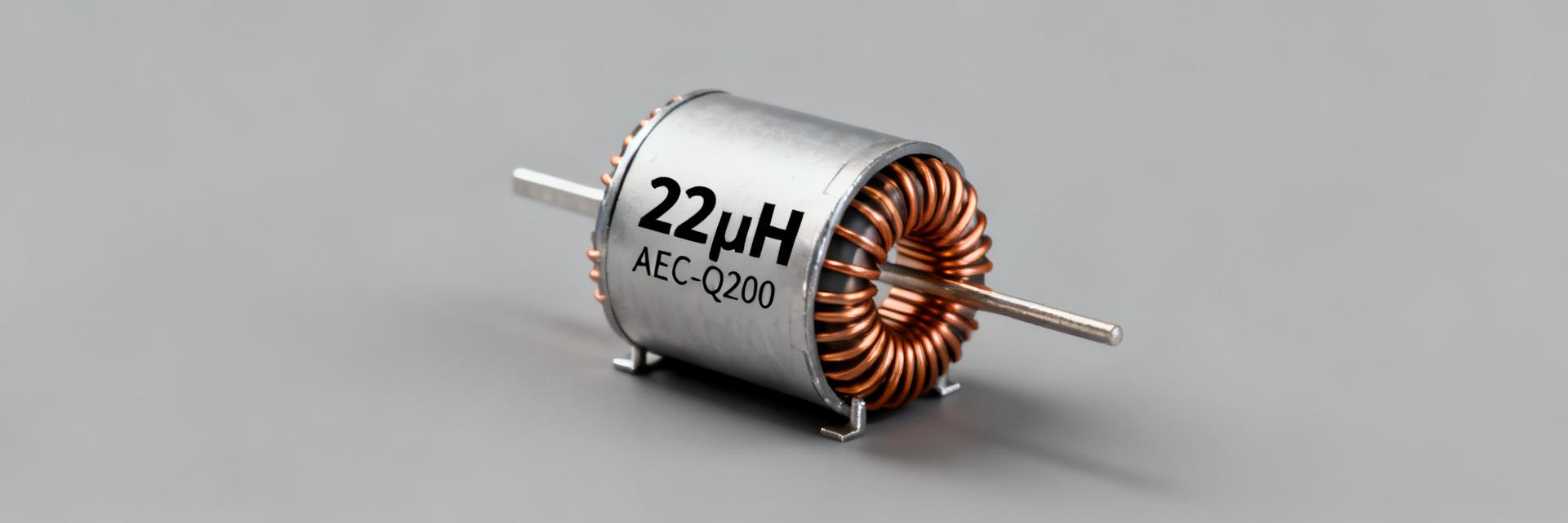
Point: According to consolidated component records, 784773122 is specified as a 22 µH, AEC‑Q200‑qualified wirewound power inductor in a PD2A-style SMT package — essential details engineers need for automotive and power‑conversion designs.
Evidence: Manufacturer datasheet entries and qualification notes report nominal inductance, current ratings and package constraints that drive selection decisions.
Explanation: This article provides a concise, data‑first cross‑reference and spec breakdown so designers can identify, compare, test and source true equivalents for 784773122 while understanding the practical tradeoffs in application.
1 — Overview & key specs at a glance (Background introduction)
1.1 — Core electrical parameters
Point: Primary electrical parameters to check are inductance (22 µH nominal), tolerance, DC resistance (RDC), rated/ saturation current, self‑resonant frequency (SRF) and Q factor.
Evidence: Typical power inductors in PD2A footprints list RDC in the milliohm range, Isat and Irms as separate values, and SRF above switching frequencies to avoid resonance.
Explanation: For power filtering and buck converters, lower RDC reduces I²R losses, higher Isat preserves inductance under load, and SRF determines usable high‑frequency behavior — all key to correct inductor specs interpretation.
1.2 — Mechanical, thermal & qualification
Point: PD2A‑style parts are compact SMT wirewound/ferrite constructs with controlled height, recommended pad layout and automotive temperature ratings.
Evidence: Qualified automotive parts carry AEC‑Q200 notes and specify operating ranges and solder/assembly constraints; footprint and height drive board placement and clearance rules.
Explanation: Mechanical footprint, thermal derating and qualification status affect PCB layout, thermal vias, and whether the part meets harsh‑environment acceptance criteria for automotive applications.
2 — Datasheet deep-dive: interpreting nominal vs. tested values (Data analysis)
2.1 — How datasheet numbers are measured
Point: Datasheet lab values are provided under defined test conditions: frequency, test current, and ambient temperature — and will include typical vs. maximum columns.
Evidence: L vs I curves, impedance vs frequency plots and temperature coefficients clarify how inductance shifts under current and temperature stress.
Explanation: Reading graphs (L vs I shows saturation; impedance vs f shows SRF) lets designers translate nominal specs into expected behavior in their switching environment rather than assuming ideal behavior.
2.2 — Practical margining: derating curves
Point: Apply derating rules: use a conservative fraction of rated current to avoid saturation and thermal rise — commonly 50–70% depending on cooling and ambient conditions.
Evidence: Datasheet Isat refers to the current at which L falls by a specified percentage; rated current/Irms denotes thermal limits under steady state.
Explanation: Design margining balances efficiency and reliability: select inductors with higher Isat for inrush or transient‑heavy rails, and allow RDC headroom to control temperature rise.
3 — Cross-reference & equivalents (Data analysis / Case)
3.1 — How to find true equivalents: True equivalence requires matching electrical and mechanical parameters, not only package outlines; prioritize inductance±tolerance, RDC, Isat/Irms, SRF and footprint. A checklist approach prevents false drops based on part numbering alone. When searching for a 784773122 equivalent inductor, use long‑tail queries that specify 22 µH, AEC‑Q200, PD2A footprint and the critical electrical bounds.
3.2 — Comparison table blueprint
| Parameter | Target Spec (784773122) | Equivalent Requirements |
|---|---|---|
| Inductance | 22 µH | Match Nominal @ Test Freq |
| RDC (Max) | Milliohm Range | ≤ Original Max RDC |
| Isat / Irms | Application Specific | ≥ Original Ratings |
| Package | PD2A SMT | Identical Pad Layout |
| Qualification | AEC-Q200 | Required for Automotive |
Explanation: This column set enables quick filtering by electrical fit, thermal/qualification suitability and drop‑in compatibility for prototype and production phases.
4.1 — Selection Guide
Point: Map application to priority parameters: input filters prioritize SRF and current handling, output chokes emphasize RDC and ripple.
Explanation: For high‑efficiency buck outputs pick low RDC; for noisy inputs prioritize SRF above switching harmonics; for automotive pick AEC‑Q200 qualified options.
4.2 — PCB Layout Tips
Point: Layout choices control thermal performance and EMI: place the inductor close to the MOSFET/capacitor loop.
Explanation: A compact current loop, proper pad geometry and clearance to return paths reduce radiated emissions and heating; treat PD2A footprints as heat‑sensitive elements.
5 — Testing, validation & reliability checks
5.1 — Bench tests: Verify samples with LCR meter (L vs frequency), milliohm meter for RDC, current ramp tests for saturation and thermal rise under rated current. Define acceptance criteria (e.g., L within tolerance at operating current) and record L vs I to detect imminent saturation issues.
5.2 — Long-term reliability: Perform burn‑in, thermal cycling and mechanical stress tests for automotive applications. Establish change thresholds: if inductance shifts or RDC increases significantly, trigger supplier verification.
6 — Procurement & Lifecycle
6.1 — Sourcing checklist: Before procurement confirm the latest datasheet revision, lot consistency, MOQ risks and qualification status. Inspect mechanical dimensions and validate qualification claims before production use of 784773122.
6.2 — Quick implementation: Final checklist: lock PCB footprint, document key electrical acceptance tests in the BOM, plan prototype tests and define production verification steps. This reduces the risk of field failures.
Summary
- Confirm core electricals: verify 22 µH nominal, acceptable RDC range, Isat/Irms and SRF on the datasheet; these inductor specs determine suitability.
- Prioritize thermal/qualification: for automotive use require AEC‑Q200 adherence and apply conservative derating to avoid saturation.
- Validate with tests: perform L vs I, RDC, and thermal rise tests on samples to ensure real‑world performance meets production expectations.
Frequently Asked Questions
What are the key specs to verify when evaluating 784773122?
Check inductance tolerance, RDC, Isat (saturation) and Irms (thermal current), SRF, package dimensions and qualification notes. Confirm test conditions on the datasheet (frequency, test current) and use L vs I curves to ensure the part maintains inductance under expected load.
How should I margin current for reliability in automotive applications?
Use conservative derating — commonly 50–70% of rated current depending on cooling and ambient expectations. Consider peak transients and inrush; choose parts with higher Isat margins and verify thermal rise under expected duty cycles to maintain long‑term reliability.
What bench tests confirm the inductor specs are genuine?
Run an L vs frequency sweep with an LCR meter, measure RDC via four‑wire method, perform a controlled current ramp to observe saturation and measure temperature rise under rated current. Compare results to datasheet curves and acceptance thresholds defined in the BOM.


