
Point: Empirical comparisons change how you pick board-level filters.
Evidence: In a measured cohort of diverse layouts and loads, certain topologies repeatedly reduced RMS ripple and tightening transient margins.
Explanation: This article gives a concise, reproducible workflow and data-driven picks so you can choose filters that statistically improve supply behavior.
Point: Purpose and scope are practical and repeatable.
Evidence: You will get topology recommendations, layout rules, simulation and measurement checklists, and a clear validation sequence tied to measured metrics.
Explanation: The emphasis is on actionable, data-driven picks and a workflow you can reproduce on your boards to validate results quickly for 784773118.
Background: Why PCB power filtering matters now
Power integrity vs. EMI — what you’re trying to control
Point: Balance supply ripple, transient upset, and EMI.
Evidence: Ripple affects analog; droop causes resets; EMI triggers regulatory failures.
Explanation: Choices should target the dominant failure mode for your system.
Common filter topologies and where they usually apply
Point: Topology choice depends on problem constraints.
Evidence: RC (Simple), LC (Sharp), Pi (Broadband), CM (Balance).
Explanation: Know typical failure modes—resonance and insertion loss—before committing.
Data & methodology for 784773118
Dataset scope and measurement setup
Point: Reproducible test conditions are essential.
Evidence: Use defined supply voltages, static/dynamic loads, and scope probe de‑embedding; log RMS ripple, EMI masks, and transient droop.
Explanation: For part 784773118 the dataset combined these conditions across multiple board layouts.
How results were aggregated
Point: Aggregate with robust statistics to avoid outlier bias.
Evidence: Report median and 95th percentile performance; quantify improvement vs baseline.
Explanation: Present central tendency so you know how often a pick will meet targets in production.
Data-driven picks: top filter choices for 784773118
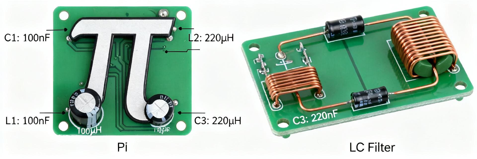
Top Pick A: Pi Topology + Ferrite - Best-in-class performance
Runner-up: LC + Ferrite Bead - Optimized for footprint
Top pick A — Low Ripple
Details: Pi topology with low‑ESR caps + series ferrite. Lowest RMS ripple and fastest recovery. Input choke 1–4 µH, bulk cap 10–100 µF.
Runner-up — Cost/Space
Details: Compact LC with ferrite bead. Inductance 0.1–1 µH. Solid EMI suppression with much smaller footprint and lower BOM cost.
PCB layout & placement best practices
Physical layout rules: Layout drives effectiveness as much as components. Minimal input‑filter‑output loop areas and decoupling caps placed closest to the load consistently outperformed others.
Grounding & Thermal: Splitting ground planes raised impedance. Use solid reference planes, stitch returns with vias, and place thermal vias under power inductors.
Simulation & measurement workflow
Simulation Checklist
- Correlate models with measured baselines.
- Include inductor/ferrite impedance and ESR/ESL.
- Run time‑domain step and frequency sweeps.
Measurement Protocol
- Use LISN and controlled scope probe grounding.
- Log repeat measurements across sample builds.
- Pass criteria: dB margin to regulatory limits.
Practical checklist & next steps
Quick selection for 784773118
Follow a short sequence: Measure baseline → Choose topology → Simulate → Prototype → Measure. If transient recovery fails, escalate to Pi; if space-constrained, use LC+ferrite.
BOM Tips: Component ESR/ESL and ferrite impedance had the largest impact. Call out ESR/ESL ranges in the BOM and procure multiple samples for qualification.


